Pre-Commissioning Checklist for Oil-Filled Power Transformers
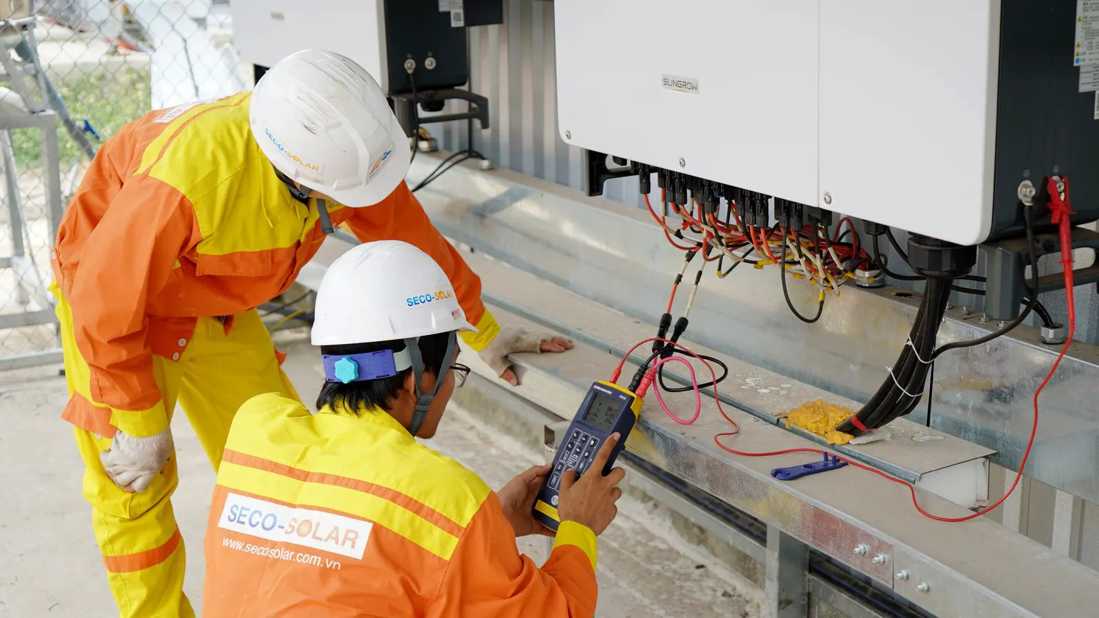
Pre-energizing an oil filled power transformer requires a structured audit of oil quality, insulation testing, and mechanical checks. This checklist helps engineers confirm that all commissioning steps are complete to prevent immediate faults and ensure safe grid connection.
- Verify oil sample results for moisture and dissolved gas levels before filling the tank
- Confirm insulation resistance and tan delta readings meet manufacturer tolerances
- Check mechanical clearances and grounding connections before applying voltage
- Ensure all protection relays are programmed and trip-tested
- Document every test result for the commissioning file
Why Pre-Commissioning Matters
An oil filled power transformer is a high-value asset that faces thermal and electrical stress from the moment it connects to the grid. If a fault exists before energization, it often manifests immediately. This can damage the winding, the bushings, or the protection system. The initial inrush current can be six to eight times the rated current. Without proper protection settings and verified insulation, that surge can push a marginal joint into failure or arc across a gap that was only marginally safe during testing.
The pre-commissioning phase is the final barrier between a factory-built unit and live service. It is not just about running tests. It is about confirming that the installation matches the design and that no component is compromised by handling or transport. Transport involves vibration, tilting, and temperature changes. The core clamping bolts can loosen. The bushing oil level can shift. The oil itself can absorb moisture from humid air if a seal fails during loading.
This checklist is designed for site engineers and commissioning teams. It groups tasks by theme to make the audit copyable and auditable. Each item corresponds to a specific point of failure that has historically caused premature transformer outages.
Oil and Insulation Quality Checks
The oil inside the transformer is the primary insulation medium. Before you energize the unit, you must know the condition of the oil. The oil separates the winding from the tank, carries heat away from the hot spots, and prevents corona discharge. If the oil is contaminated, the entire electrical performance of the unit degrades.
-
Visual Inspection of Oil Level: Check the sight glass or level indicator. The level must be within the manufacturer’s specified range for the ambient temperature. Low oil can expose the top of the winding to air. High oil can cause overflow during thermal expansion. Pay attention to the temperature of the oil at the time of inspection. A level that looks correct in hot weather may be too low for winter service.
-
Oil Sample Analysis: Collect a sample from the bottom drain valve. Test for moisture content, dissolved gas, and acidity.
- Red Flag: Moisture above 20 ppm (parts per million) at the time of testing.
- Red Flag: High levels of hydrogen or acetylene indicating internal arcing or thermal issues.
- Red Flag: High acidity indicating the oil is degrading its cellulose paper insulation.
Sample collection is critical. Use a clean, dry container. Do not sample from a valve that has been open to the air for hours.
-
Insulation Resistance Test: Use a megger to measure the insulation resistance between the winding and the tank.
- Red Flag: Values significantly lower than the baseline or previous tests.
- Red Flag: A drop in insulation resistance over time during the test, which indicates moisture absorption.
Perform the test at a steady temperature. Insulation resistance is highly temperature dependent. Compare results to the factory test report at the same temperature. If the site temperature is much lower than the factory temperature, the resistance will be higher.
-
Tan Delta (Dissipation Factor) Test: This test measures the quality of the insulation. It detects moisture and aging.
- Red Flag: A tan delta value higher than the manufacturer’s limit or a significant difference between the low-voltage and high-voltage windings.
- Red Flag: A high tan delta on one phase but not the others. This points to a localized problem, such as a wet winding pack.
Tan delta is more sensitive to moisture than insulation resistance. A winding can pass the insulation resistance test and still have a high tan delta if the paper insulation is wet.
-
Partial Discharge Test: If the specification requires it, perform a partial discharge test. This finds weak spots in the insulation that standard resistance tests might miss.
- Red Flag: Any discharge level above the threshold defined in the technical agreement.
- Red Flag: Discharge detected at low applied voltage.
Partial discharge occurs when the electric field in the insulation is high enough to ionize air or gas bubbles. It is a precursor to a full breakdown. The test requires specialized equipment and a controlled environment.
Electrical Testing and Verification
Once the oil is confirmed clean and the insulation is sound, you move to electrical verification. These tests confirm that the transformer is electrically correct.
-
Winding Resistance Measurement: Measure the DC resistance of each phase. This checks for broken strands or loose connections.
- Red Flag: A percentage difference between phases that exceeds the tolerance specified in the IEC or IEEE standards.
- Red Flag: Resistance values that do not match the factory test report.
A single broken strand in a winding can cause uneven heating and premature failure. The test requires a stable connection. Use low resistance measurement equipment with four-wire connections to eliminate lead resistance errors.
-
Turns Ratio Test: Verify the turns ratio between the high-voltage and low-voltage windings.
- Red Flag: A ratio that deviates from the nameplate value.
- Red Flag: A mismatch in the ratio between phases.
A turns ratio error means the transformer will not deliver the correct voltage. It can trip the protective relays or damage downstream equipment. The test is performed at low voltage to avoid heating the windings.
-
No-Load Loss Measurement: If the transformer is rated for it, measure the no-load loss.
- Red Flag: Losses significantly higher than the guaranteed value.
- Red Flag: A high loss on one phase compared to the others.
No-load loss is primarily due to hysteresis and eddy currents in the core. A high value can indicate a defect in the core clamping or a shorted core turn.
-
Short-Circuit Impedance Check: This is often done at the factory, but verify the data sheets match the delivered unit.
- Red Flag: Impedance values that differ from the factory report.
- Red Flag: An asymmetrical impedance between phases.
Short-circuit impedance determines the breaker coordination and the voltage drop under load. A mismatch can cause the protection system to operate incorrectly during a fault.
| Test Type | Purpose | Typical Red Flag |
|---|---|---|
| Oil Moisture | Detects water contamination | >20 ppm moisture |
| Insulation Resistance | Checks for leakage paths | Low or dropping resistance |
| Tan Delta | Measures insulation quality | High dissipation factor |
| DC Resistance | Finds loose or broken strands | Phase imbalance |
| Turns Ratio | Verifies voltage transformation | Deviation from spec |
Mechanical and Structural Inspections
The electrical system is only as good as the metal that holds it. Mechanical defects can cause thermal stress, oil leakage, or fire hazards.
-
Bushing Inspection: Check the oil and gas seal on the bushings. Ensure the oil level in the bushing is correct.
- Red Flag: Weeping oil at the seal.
- Red Flag: Cracks in the ceramic or glass insulator.
- Red Flag: Low oil level in the bushing reservoir.
The bushing is a separate insulation path. It must be filled to the correct level for the ambient temperature. A low oil level in the bushing can cause the insulator to overheat and crack.
-
Cooling System Check: Inspect the radiators or cooling fans.
- Red Flag: Loose mounting brackets.
- Red Flag: Debris blocking airflow.
- Red Flag: Leaking radiators.
The cooling system is critical for thermal management. If the radiators are blocked or the fans are not working, the transformer will overheat. Overheating degrades the insulation paper and shortens the life of the unit.
-
Grounding Connections: Verify that the tank, the core, and the shield are all bonded to the site earthing system.
- Red Flag: Loose lugs or rust on the connection points.
- Red Flag: Missing bonding jumpers.
- Red Flag: High resistance at the connection point.
A poor ground can lead to dangerous voltages on the tank during a fault. It can also cause circulating currents in the shield, which generate heat and damage the insulation. Use a low resistance ohmmeter to verify the grounding connection.
-
Clearance Check: Measure the air gaps between the transformer and nearby structures.
- Red Flag: Objects closer than the minimum clearances specified for the voltage class.
- Red Flag: Insufficient clearance for the bushing flashover.
Clearances are determined by the voltage class and the altitude. If the transformer is installed at high altitude, the required clearances increase. Insufficient clearance can cause a flashover during a lightning strike or a fault.
Protection and Control System Setup
Before you close the disconnect switch, the protection system must be ready to react. The protection system is the first line of defense against a fault. If it fails, the transformer can be destroyed.
-
Relay Programming: Load the protection relays with the final settings.
- Red Flag: Settings that do not match the single-line diagram.
- Red Flag: Missing coordination settings with upstream feeders.
- Red Flag: Incorrect pickup values or time settings.
The relay settings must be coordinated with the rest of the system. If the relay trips too late, the fault will damage the transformer. If it trips too early, it will cause unnecessary outages. Use the site single-line diagram and the coordination study to verify the settings.
-
Trip Testing: Perform a trip test on the overcurrent and earth fault relays.
- Red Flag: The breaker does not operate when a test signal is applied.
- Red Flag: The relay does not trip at the expected pickup value.
- Red Flag: The breaker trips at the wrong time.
The trip test confirms that the relay can actually open the breaker. It tests the entire chain: relay, trip unit, and breaker. If the breaker does not open, the fault will continue to flow.
-
Control Circuit Verification: Check that the local and remote control circuits are functioning.
- Red Flag: The breaker cannot be opened or closed manually.
- Red Flag: The remote control signal does not work.
- Red Flag: The local control switch is stuck.
The control circuit must be reliable. If the breaker cannot be opened manually, you cannot isolate the transformer for maintenance. If the remote control fails, you cannot operate the breaker from the substation.
-
Instrumentation Check: Verify that the temperature sensors, oil level sensors, and pressure switches are sending the correct signals to the PLC or DCS.
- Red Flag: A sensor reading that does not match a manual check.
- Red Flag: A sensor that gives a constant reading.
- Red Flag: A pressure switch that does not trip at the expected pressure.
The instrumentation provides the data needed to monitor the transformer during operation. If the temperature sensor is faulty, you will not know if the transformer is overheating. If the oil level sensor is faulty, you will not know if the oil is leaking.
Final Documentation and Sign-Off
The last step is paper work. Without it, you do not have a commissioning file. The documentation is the record of the work performed. It is the basis for future maintenance and troubleshooting.
-
Test Reports: Gather all test reports. These include the oil analysis, insulation tests, and relay settings.
- Red Flag: Missing test data or unsigned reports.
- Red Flag: Reports that do not match the test equipment used.
- Red Flag: Missing calibration certificates for the test equipment.
The test reports must be complete and signed by the test engineer. They must include the date, time, ambient conditions, and test equipment used. This information is critical for interpreting the results.
-
Nameplate Verification: Confirm that the nameplate data matches the technical agreement.
- Red Flag: A mismatched serial number or rating.
- Red Flag: A nameplate that is damaged or illegible.
- Red Flag: A nameplate that does not match the test reports.
The nameplate is the official record of the transformer’s specifications. If the nameplate does not match the technical agreement, the transformer may not be suitable for the installation.
-
Safety Sign-Off: Ensure all personnel are cleared for the energization.
- Red Flag: Missing PPE or incomplete safety briefings.
- Red Flag: Personnel who do not understand the hazards.
- Red Flag: Missing lockout/tagout procedures.
Safety is the top priority. Before you energize the transformer, you must be sure that everyone is aware of the hazards and that the safety procedures are in place.
Common Mistakes to Avoid
- Skipping the Oil Sample: Many teams assume the oil is clean because it was clean in the factory. Transport and handling can introduce moisture. Always sample the oil at the site.
- Ignoring Tan Delta: A good insulation resistance reading does not guarantee good insulation quality. Tan delta catches what resistance misses. Always perform the tan delta test.
- Rushing the Grounding Check: A poor ground can lead to dangerous voltages on the tank during a fault. Always verify the grounding connection with a low resistance ohmmeter.
- Forgetting the Bushing Oil: The bushing is a separate oil system. If the bushing oil is low, the insulator may fail even if the main tank is full. Always check the bushing oil level.
- Assuming the Relay is Ready: The relay is a separate device. It must be programmed and tested independently. Always perform a trip test.
When to Stop the Process
If you encounter a red flag, stop the commissioning process. Do not energize the transformer with unresolved issues. A transformer with a defect can cause a major outage.
- Oil Moisture: If the moisture is high, the transformer must be dried. This can take days or weeks.
- Insulation Failure: If the insulation resistance is low, the transformer may need to be opened and dried or replaced.
- Mechanical Defect: If a bushing is cracked, it must be replaced. A cracked bushing is a fire hazard.
Stop the process. Document the issue. Contact the manufacturer.
Final Words
Pre-commissioning is not a formality. It is a risk management exercise. The oil filled power transformer is a complex machine. It requires a careful audit before it meets the grid.
Use the checklist above. Verify every item. Keep the documentation. The transformer will serve you for decades if you start its life correctly.
Frequently asked questions
What is the most common reason for transformer failure during pre-commissioning?
Moisture in the oil is the most common cause. It degrades the insulation and can lead to immediate discharge when voltage is applied.
How often should oil samples be taken during commissioning?
Typically, one sample is taken after the oil is filled and one after the drying process. Additional samples are taken if the oil level is adjusted or if there is any suspicion of contamination.
Can a transformer be energized if the tan delta test fails?
No. A failed tan delta test indicates poor insulation quality. The transformer should not be energized until the issue is resolved and the test is repeated.
What is the role of the bushing oil in the system?
The bushing oil provides insulation for the high-voltage terminal. It is separate from the main tank oil and must be maintained at the correct level and quality.
Is a partial discharge test always required?
It depends on the voltage class and the technical agreement. For high-voltage transformers, it is often required. For lower-voltage units, it may be optional. Always check the specification.