Distribution Transformer Sizing: Load and Voltage Guide
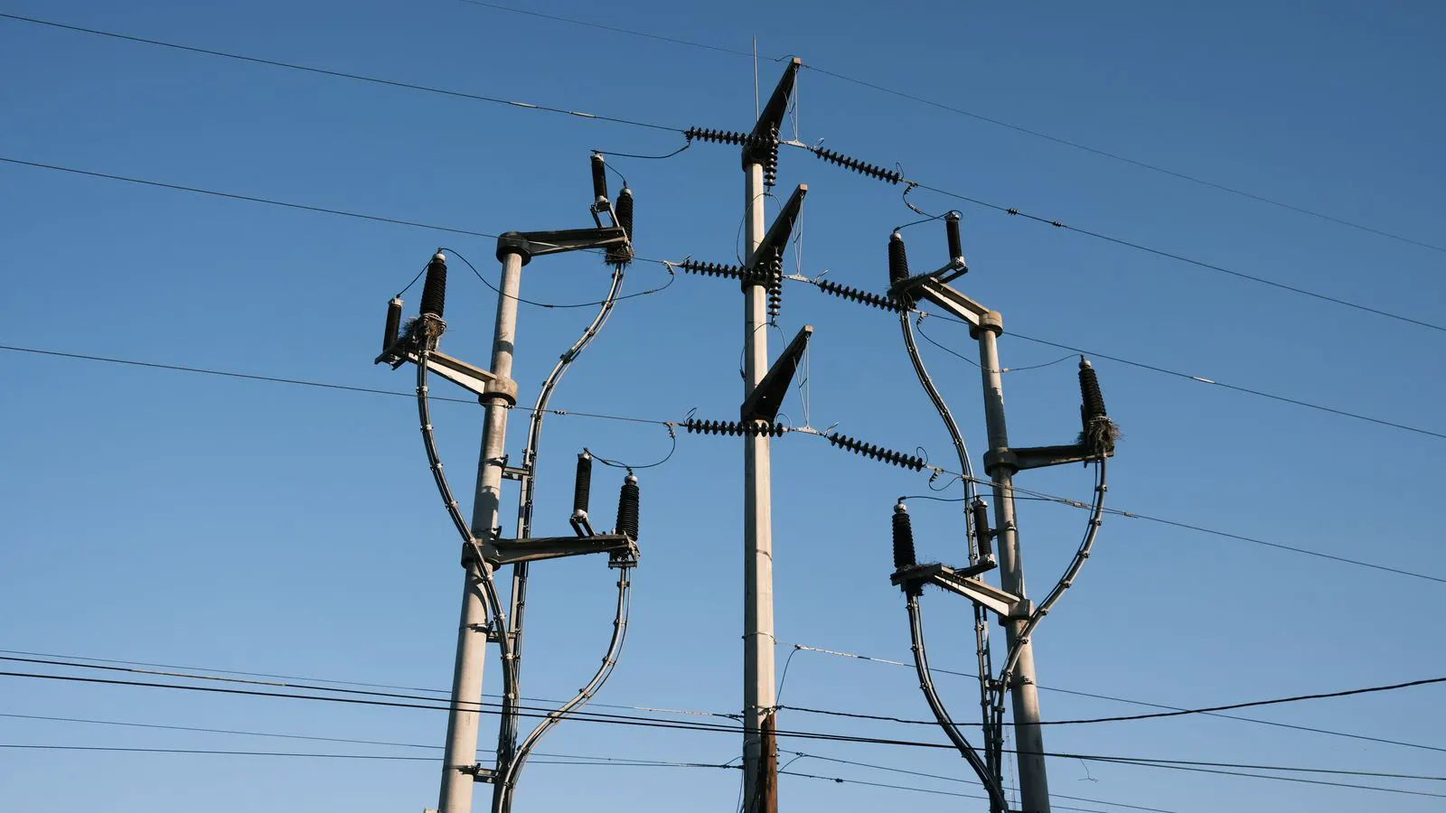
Distribution transformer sizing requires calculating total load in kVA, adding a margin for growth, and verifying voltage drop across the secondary wiring. The final rating must match the primary voltage and the site's specific power factor.
- Sizing starts with converting all connected loads to a common kVA value.
- The selected kVA rating must accommodate future load growth without triggering excessive voltage drop.
- Voltage drop limits the distance between the transformer and the farthest load point.
- The power factor of the facility directly affects the required kVA rating for a given kW load.
- A mismatched transformer can cause overloading, high current draw, or unstable voltage at the customer end.
What drives the kVA rating?
The kVA rating of a distribution transformer is not a guess. It is a calculated number based on the actual electrical demand of the site. The rating represents the maximum apparent power the unit can handle without exceeding its thermal limits. If the load exceeds this rating, the copper windings heat up. The insulation degrades. The transformer trips its overcurrent protection or, in worse cases, suffers permanent damage.
The calculation hinges on three inputs. The first is the total kW of all connected equipment. The second is the power factor of the load. The third is the anticipated growth of the load over the transformer’s service life. You cannot simply add up the kW of motors, lights, and machinery. You must account for the fact that not all power is used immediately. The power factor determines how much reactive power the system requires. A low power factor means the transformer must supply more current to deliver the same amount of real power.
A common mistake is sizing based solely on the current demand. While current is a valid check, it does not account for the thermal history of the unit. A transformer operating at 90 percent of its rating for a short burst is different from one running at 80 percent for twenty-four hours. The thermal model of the transformer assumes a steady state. The load calculation must reflect the average sustained load, not just the peak start-up current of a single motor.
How do you sum the load?
Start by listing every piece of equipment connected to the distribution system. This includes permanent machinery, lighting, HVAC systems, and any future additions planned for the next five to ten years. For each item, identify the nameplate rating. If the nameplate is in kW, you are half way there. If it is in kVA, the power factor is usually listed. If it is in amps, you must convert it using the voltage and power factor.
For a single-phase load, the formula is straightforward. Multiply the voltage by the current and by the power factor to get kW. To get kVA, multiply voltage by current. For a three-phase load, multiply by the square root of three. The power factor is the ratio of kW to kVA. This means that a motor with a low power factor requires a larger kVA rating than a resistive load of the same kW.
Consider a facility with a total installed load of 500 kW. If the power factor is 0.90, the required kVA is roughly 556 kVA. If the power factor drops to 0.80, the required kVA rises to 625 kVA. This difference is significant. It means the transformer must be physically larger, and the conductors must be thicker to handle the higher current.
You must also apply a diversity factor. Not all loads operate at maximum capacity simultaneously. A bank of small motors in an office building will rarely all start at once. A heavy industrial plant with large compressors may see a higher concurrent demand. Engineering standards provide guidance on these factors, but a conservative approach is to add a margin for growth. A typical margin is 10 to 20 percent of the calculated load. This buffer accounts for unplanned expansions or new equipment that was not in the original design phase.
How does voltage drop affect the choice?
Voltage drop is the reduction in voltage between the transformer secondary terminals and the farthest load point. It is caused by the resistance and reactance of the distribution wiring. If the voltage drop is too high, the equipment at the end of the line may not operate correctly. Motors may draw excessive current. Sensitive electronics may malfunction or shut down.
The allowable voltage drop is usually set by local utility codes or internal standards. A common limit is 3 to 5 percent for the entire distribution system. You must calculate the drop based on the length of the cable and the current flowing through it. The current is higher when the power factor is lower. This creates a feedback loop. To reduce the voltage drop, you might increase the conductor size. But if the transformer is undersized, the current is high, and the voltage drop increases.
A smaller distribution transformer often has a lower impedance. This can actually help with voltage regulation, but only if the transformer is not overloaded. An overloaded transformer operates at a lower point on its voltage regulation curve. The voltage at the secondary terminals drops significantly under load. This makes it harder to maintain a stable voltage at the load end.
When sizing the transformer, you must consider the distance to the farthest load. A 100 kVA transformer might be fine for a short run to a building. The same transformer might fail to maintain voltage for a long run to a remote pump station. In such cases, you might choose a larger transformer to reduce the current draw, or you might increase the conductor size. The decision depends on cost and space. A larger transformer costs more. Larger conductors cost more to run and may require more room in the conduit or cable tray.
What role does the power factor play?
The power factor is a measure of how effectively electrical power is converted into useful work. A resistive load, like a light bulb or a heater, has a power factor of 1.0. An inductive load, like a motor or a transformer, has a power factor less than 1. The difference is reactive power. Reactive power circulates between the source and the load. It does not do useful work, but it occupies capacity in the transformer and the wires.
If the power factor of the site is low, the transformer must be larger. You can improve the power factor by adding capacitors. These capacitors provide the reactive power locally, reducing the current drawn from the transformer. This has two benefits. The transformer can be smaller. The voltage drop in the wires is reduced.
However, you must be careful with power factor correction. If you add too many capacitors, the power factor can become leading. This can cause overvoltage issues. The utility may require a minimum power factor. In many regions, the utility may require the customer to maintain a power factor above 0.90. This requirement is often tied to the billing of the facility. A low power factor can result in a penalty fee.
When sizing the transformer, assume the worst-case power factor for the current load, but plan for the best-case scenario with correction. If you plan to install power factor correction, you can size the transformer for the corrected power factor. If you do not plan to correct it, you must size for the existing low power factor.
How do you select the standard kVA rating?
Transformers are manufactured in standard ratings. You cannot buy a transformer with an arbitrary kVA number. You must select the nearest standard rating that exceeds your calculated requirement. The standard ratings vary by manufacturer and region, but they generally follow a progression. For distribution transformers, common ratings include 25, 50, 75, 100, 150, 250, 300, 400, and 500 kVA.
If your calculated requirement is 120 kVA, you would select a 150 kVA unit. This gives you a margin of 20 percent. If your calculated requirement is 148 kVA, you would select a 150 kVA unit, but you would be operating very close to the limit. You would have no room for growth. You would be at risk of overloading during peak summer or winter months.
It is better to oversize slightly than to undersize. An oversized transformer may have lower efficiency, but it will last longer. It will handle the load with ease. An undersized transformer will run hot. It will trip its protection devices. It will require replacement sooner. The cost of a transformer is not the only cost. The cost of downtime, the cost of replacement, and the cost of repair are significant.
What about efficiency and losses?
Every transformer loses energy. This loss occurs in the copper windings and the magnetic core. The copper loss is proportional to the square of the current. The core loss is proportional to the voltage. The total loss is the sum of these two components. The efficiency of the transformer is the ratio of output power to input power.
A higher efficiency transformer wastes less energy. This saves money on the utility bill. However, higher efficiency transformers are usually more expensive. They are also larger. The trade-off depends on the load profile. If the transformer operates at a high load factor for many hours, the savings from higher efficiency can offset the higher purchase price. If the transformer operates at a low load factor, the savings are minimal.
For distribution transformers, the efficiency is usually not the primary driver for sizing. The primary drivers are capacity and voltage regulation. However, you should consider the efficiency when comparing two transformers of the same kVA rating. A higher efficiency unit is a better long-term investment.
How do you verify the sizing?
Once you have selected a kVA rating, you must verify it against the site conditions. Check the primary voltage. The transformer must match the utility supply voltage. If the utility supplies 13.8 kV, you need a 13.8 kV primary transformer. If you buy a 12 kV transformer, it will overvoltage. The insulation will degrade. The core will saturate.
Check the secondary voltage. The transformer must match the voltage required by the load. A 480 V secondary is common for industrial loads. A 208 V secondary is common for commercial loads. A 120/240 V secondary is common for residential loads. You can use a tapped transformer to adjust the secondary voltage if needed.
Check the impedance. The impedance of the transformer affects the voltage regulation. A lower impedance transformer has better voltage regulation. However, a lower impedance transformer has higher short-circuit current. This requires larger fuses or circuit breakers. You must coordinate the transformer impedance with the protection devices.
Finally, check the cooling. A transformer can be air-cooled or oil-cooled. For distribution transformers, air-cooled is common. It is cheaper and simpler. Oil-cooled is used for larger ratings. It provides better thermal management. If the site is in a hot climate, you may need a transformer with a higher temperature class. The ambient temperature affects the capacity of the transformer. A transformer rated for 40 C ambient will have a lower capacity if the ambient temperature is 50 C. You must derate the transformer based on the ambient temperature.
Frequently asked questions
Can I just use the sum of the nameplate kW to size the transformer?
No, you must convert kW to kVA using the power factor. A low power factor increases the kVA requirement. You should also add a margin for load growth.
How much margin should I add to the calculated load?
A margin of 10 to 20 percent is typical for distribution transformers. This accounts for future expansion and peak load variations.
Does the transformer voltage rating matter for sizing?
Yes, the transformer must match the primary supply voltage and the secondary load voltage. A mismatch causes overvoltage or undervoltage and can damage the equipment.
Is a larger transformer always better?
Not necessarily. A larger transformer has higher no-load losses and a higher purchase price. It is better to size close to the load with a reasonable margin.
How does voltage drop affect the transformer size?
Higher current draw causes more voltage drop. To reduce voltage drop, you might need a larger transformer to reduce the current, or you might need larger conductors.